autocad making a 3d revolve object from 2d drawing
AutoCAD Revolve
The Revolve command in AutoCAD 3D is used to create a 3D solid or surface by sweeping the object through its axis at a predefined angle.
The paths and objects that can be revolved are:
- Planar
- Non-planar
- Open up
- Airtight
- Solid
- Surfaces
- Circles
- Arcs
The positive direction of rotation is adamant past the correct-mitt thumb rule.
We tin can rotate the object with respect to X-axis, Y-axis, and Z-centrality.
We are required to use polyline to create a base for revolve command.
We can either join the lines or segments before revolving.
Notation: For meliorate agreement, try to make the base to revolve in TOP view control.
Consider the below prototype:
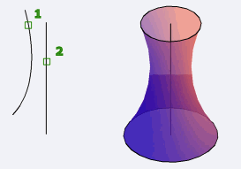
Let's empathize with few examples.
Example ane:
To revolve with respect to X, Y, or Z-axis.
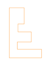
Consider the below 2D object:
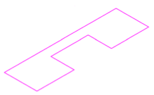
Brand certain to actuate the ortho mode.
The to a higher place object is drawn in SE Isometric Mode.
The in a higher place object was start joined.
Place the UCS icon on the object.
The steps are listed below:
one. Create the to a higher place figure.
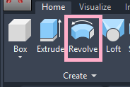
ii. Select Revolve icon from the ribbon console, as shown below:
Or
Blazon REV or revolve on the command line or command prompt and press Enter.
three. Select the object to circumduct with a small square cursor, equally shown below:

iv. Press Enter.
5. Specify the Ten, Y, or Z axis.
If X-axis is selected:
If Z-axis is selected:
6. Press Enter.
seven. Specify angle of revolution.
8. Printing Enter.
To circumduct according to the axis line, follow the below steps:
i. Blazon REV or revolve on the command line or control prompt and press Enter.
ii. Select the object to revolve with a small square cursor, as shown below:
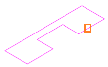
iii. Printing Enter.
four. Specify centrality start point of the object to be revolved.
5. Specify centrality endpoint.
half-dozen. Specify angle of revolution.
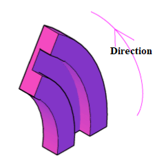
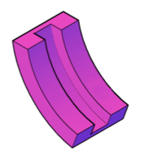
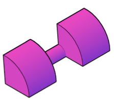
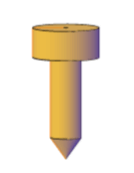
If the specified angle = 30, the object will look like the below image:
If the specified angle = 360, the object will look like the below paradigm:
If the specified angle is 95, the object will look like the below prototype:
vii. Printing Enter.
To revolve as a surface, follow the below steps:
1. Type REV or circumduct on the command line or command prompt and printing Enter.
two. Type M or mode on the command line < printing Enter.
3. Blazon Surface or S on the command line < press Enter.
4. Select the object to circumduct with a small square cursor, as shown below:

five. Press Enter.
vi. Specify centrality start point of the object to be revolved.
seven. Specify axis endpoint.
8. Specify bending of revolution.
If the specified angle = 30, the object will look like:
9. Press Enter.
We tin can easily notice the difference between the surface and solid.
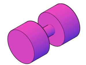
Example 2:
The base of operations is created in 2d Height view command.
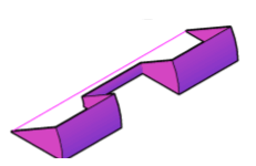
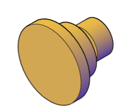
Consider the below object:

Change TOP view command to SE Isometric, as shown below:
Use Revolve command and specify the showtime and finish axis. Specify angle = 360.
The object will appear as:
Other view of the object is shown below:
Y'all tin alter the angle value according to the requirements.
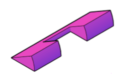
Example 3:
The base is created in 2d Top view command.
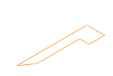
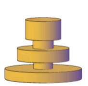
Consider the below object:
Modify TOP view control to SE Isometric, every bit shown below:

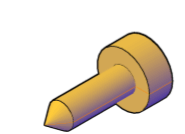
Apply Circumduct command and specify the start and terminate axis. Specify angle = 360.
The object volition appear as:
Other view of the object is shown below:
You tin change the angle value according to the requirements.
Similarly, we tin create many objects.
The views of the object can also be adapted by the Orbit command.
The system variable named as SURFACEMODELINGMODE can be used to extend the surfaces as procedural or NURBS surfaces.
andersonfropeorcee.blogspot.com
Source: https://www.javatpoint.com/autocad-revolve
0 Response to "autocad making a 3d revolve object from 2d drawing"
Post a Comment